Log In
 Register
 Favorites
How can we help you?
Loudspeaker Impedance
In electrical parlance, impedance, Z, is the characteristic of a device that causes a reduction in the amount of current, I, for a given voltage, V, in a circuit. It’s generally described by the equation:
Typically, this impedance is characterized by two components: resistance and reactance. Since resistance is the same under DC or AC conditions, it is usually stated at DC. However, reactance is only meaningful under AC conditions and comes in 2 main varieties: capacitance and inductance. Capacitive reactance decreases with increased frequency, whereas inductive reactance exhibits a direct proportionality with frequency.
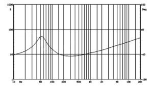
The primary source of electrical impedance in a loudspeaker driver is the voice coil. The metal wire exhibits an amount of DC resistance determined by its length, diameter, and material (often copper) and the looped path of the coil also creates an inductance. If you look at the overall shape of the impedance curve (with the exception of resonance – that aberrant peak in the curve – we’ll come back to that), it starts at the DC resistance, RE in a driver specification, and increases with frequency. This is the combination of the resistance and inductive reactance of the voice coil. The nominal impedance of the driver is typically specified at a frequency above resonance but before the inductive reactance begins to dominate.
Now, let’s get back to that resonance. There’s that noticeable increase in impedance characteristic of resonance. In fact, it’s this measurement that yields insight to the Thiele-Small parameters that play a fundamental role in designing a loudspeaker’s final enclosure for a given application. To appreciate what’s happening to the impedance curve, here, we need to remember that a loudspeaker driver is effectively an electric motor. Whenever any motor is driven, it generates a phenomenon referred to as back emf (electromotive force). This back emf opposes the flow of current – effectively an impedance.
This back emf is heavily influenced by resonance. Mechanical resonance is the point for any system where a slight disturbance causes sustained oscillations. Think of plucking a guitar string: one pluck sets the string vibrating for a significant period of time. The string vibrates at a particular frequency influenced by its physical characteristics. Ever tried sliding a wet finger around the rim of a crystal glass? That high pitched ringing is also resonance. Like guitar strings, different glasses have different resonant frequencies. Resonance in a loudspeaker is that frequency at which the cone/coil movement is greatest for a small input.
How this plays out in our impedance curve is this back emf increases with increased motor speed. Consider when you first turn on an electric motor. Initially, the lights in the room will dim but, as the motor speeds up, everything goes back to normal. Initially, the motor’s impedance is low due to a lack of back emf. As the back emf increases, so does the impedance and the motor current drops. The high “inrush” current is the reason the lights dim initially. So, at resonance, the loudspeaker motor speed peaks as does the back emf resulting in the increased impedance we see around this frequency.
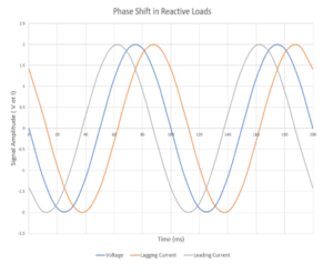
Another effect of this reactance on an AC circuit is it introduces a phase shift, where the voltage and correlating current don’t occur at the same time. When current lags voltage (voltage increases/decreases before current increases/decreases), this phase is positive. This occurs with inductive reactance. When the current leads, the phase is negative and is exhibited with capacitive reactance. This phase shift ranges from -90° to +90° and depends on the relative contributions to the impedance from resistance, inductace, and capacitance – the funkiness around resonance due to back emf notwithstanding. When the inductive and capacitive phases are equal and opposite we get a phase shift of zero.
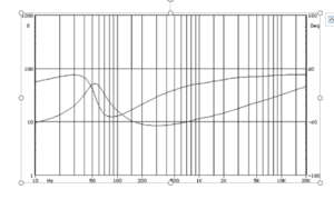
This phase information gives rise to a second line we see on a typical loudspeaker impedance curve. Again, other than at resonance, the phase tends to become positive due to the voice coil inductance. And, if you were to extend to lower frequencies than the graph typically shows, the phase goes to zero as the impedance approaches the DC resistance of the voice coil wire.

At resonance, we not only see the impedance magnitude reach a maximum value, but we also see the phase pass through zero. The inductive reactance and effects of the back emf offset each other exactly. In loudspeaker impedance curves, this maximum impedance and zero phase shift occur at the same frequency – the resonant frequency of the driver.
Adding an enclosure shifts this resonant frequency higher, while a ported enclosure shifts resonance and adds a second resonant peak due to the additional air mass moving in the port opening. The DC resistance and voice coil inductance don’t change but the back emf effects shift due to the additional constraints on the motor movement in the enclosed system.
As always, if you have any questions about how this impedance information can inform your design, please contact us and our audio engineers will be happy to lend their expertise.