Log In
 Register
 Favorites
How can we help you?
Voice Coil Assembly
- September 05, 2019
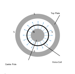
While it’s difficult to isolate any one part of a loudspeaker when it comes to ensuring proper alignment and operation, in this article, we’ll focus on the voice coil assembly. For any loudspeaker to accurately reproduce a sound source, it’s critical that the voice coil remain suspended consistently within the magnet gap between the center pole piece and the top plate. It must be able to move freely but not so far as to lose the interaction between the permanent magnet of the speaker and the varying magnetic field created by the voice coil current.
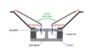
We’ve addressed the role of the surround and spider for this function in another article (A Loudspeaker Driver Breakdown). Here, we’ll consider the combined role of the voice coil assembly: the voice coil, former, and dust cap.
Voice Coil
Just as the name implies, this is a coil of wire (typically copper or aluminum) which is connected to the terminals of the driver and conducts current driven by the source signal from an amplifier stage of the overall sound system. The interesting thing about current running through a wire is that this creates a magnetic field around the wire.
Now, anyone who has ever tried to hold two magnets close together immediately discovers that they interact by mutually applying a force on each other. Brought together one way, they will attract each other rather forcefully. With enough experience we learn to keep our fingers clear of the meeting point and the blood blisters become less frequent. Flip one of the magnets around, and the magnets now appear to repel each other – again, rather forcefully.
Since part of any loudspeaker driver is a permanent magnet, the magnetic field induced around the voice coil wire interacts with the field of the permanent magnet to exert a force between the magnet and voice coil (similar to two magnets exerting a force on each other). If you’ve ever studied introductory physics, you’ll recognize Newton’s 2nd Law of motion encapsulated in the iconic equation:
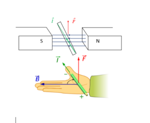
 The upshot of this expression is that any force, , acting on an object with mass, m, will accelerate at a rate, . Now, note that weird arrow-looking thing above the and variables. These indicate that the force and ensuing acceleration occur in a certain direction. And, again, in an introductory physics course, one would learn what we refer to as a right-hand rule that can be summarised by this graphic. A wire carrying current, , away from us through a magnetic field with intensity, , pointing from North to South (magnetic) experiences a force, , pointing upward. And, if we reverse the direction of the current, the force also points in the opposite direction – down, in this case.
 In the case of a loudspeaker magnet-coil interaction, this magnitude of this force is described by the expression:
That l variable in this relationship is one reason we coil the wire in the gap between the centre pole and the top plate – the North and South poles of our driver, respectively. It refers to the length of the voice coil wire that loops through the magnetic field. The strength of the magnetic field, , and the length, , of the voice coil determine an important loudspeaker parameter, the product, for determining the loudspeaker’s sensitivity. This structure meets a number of goals:
- Wire length, , can be optimised by looping the wire around several times
(voice coil wires are coated with a very thin but strong insulating layer to avoid shorting between loops) - The magnetic field remains uniform within the gap
(provided the voice coil remains in the centre of this space) - The force is maximised when the current direction is perpendicular to the magnetic field direction
(the radial magnetic field lines are always perpendicular to the circumference of the voice coil loop)
Former
So, the physics of this motor arrangement requires that we keep the voice coil in the middle of the magnet gap but it must be able to move freely (within limits) up and down within the gap. The former is a rigid cylinder around which the voice coil wire is wrapped, maintaining the circular shape of the loop. This is attached to the inside ring of the diaphragm, which is kept centred by the driver surround/spider suspension system.
Materials for formers can vary and are typically chosen to address power handling needs. Paper is common in lower power rated drivers with materials like Kapton or Nomex used for higher power loudspeakers. While the choice of material can also impact the tonal nature of the driver’s output, this usually plays a meaningful role in larger drivers, like sub-woofers.
Dust Cap
Finally, to ensure that the voice coil can continue to move freely in the gap over time, it’s imperative that the gap remain free of other obstacles. As the name implies, this is the function of the dust cap. But, like the former (although more significantly for a broader range of drivers), different materials can lend tonal characteristics to the sound output of the driver. Materials can range from paper, to rigid plastics, to rubber (naming a few). In addition to the material, the shape of the dust cap also plays a role in the tonal character of the driver. There is considerable variation here as well (e.g. simple dome, corrugated disc, dome with secondary concentric cone). Choices of dust cap shape typically influence variations in outputs at different frequencies within the passband of the driver’s frequency response curve.
As always, if you have any special voice coil assembly needs, please contact us. The superior technical support integral to the Stetron-customer design cycle helps to keep our customers satisfied.